The carburetor of Fiat 500 engine: mixture, air, starter
All of us believe that the Fiat 500 is a simple machine. It’s incredible but it hides a lot of (good) technology . Do not believe us ? I found the manual “Fiat 500 review” and the first few pages talk about the carburetor …. I scanned the whole thing and here it is .
I hope I have done something to please many fans of the Cinquino
FIAT 500 ENGINE CARBURETOR
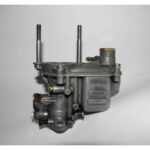
For the Fiat 500 , there are basically two models: The carburetor Weber 261MB type 4 , mounted on the Fiat 500 engine 110D.000 , a one-piece invert the carburetor Weber 26 OC type , mounted on the Fiat 500 Giardiniera engine with 120,000 , is instead a one-piece horizontal ( the two types of carburettor are fitted with a starting device operation progressive ; whose degree of insertion is established by the driver depending on the temperature of the engine, so as to allow both a ready starter that a smooth operation during the reached normal operating temperature )
WEBER CARBURETOR 4 261MB
The starter device ( Fig. 40) is costltuito from the valve (33 ) , driven by Appendix of the rocker ( 36 ) connected by a shaft , to the control lever (38 ) . Pulling all the way to the throttle control device , the lever ( 38) by means of the rocker arm ( 36) raises the valve (33 ) from its sealing seat and pushes it in the fully open position (diagram fig. 40). In this position the valve (33 ) closes the air hole (27 ) and the hole of the mixture ( 29) , while discovers both the holes of the mixture ( 30) and ( 32 ) , communicating , through the channel (26 ) , as the jet starter (46 ) , since the air holes (32) hole ( 29) can communicate with the duct of the carburetor , with the valve (33 ) in the partially open position , through the central groove of the valve itself , the channel (28 ) and the hole (31 ) formed in the diffuser (21 ) in correspondence of the restricted section . With the throttle (19 ) in the operating position to the minimum , depression , due to the suction of the engine driven by the starter motor, causes the fuel , which is located in the housing of the jet (46 ) , in the jet and in the same cockpit reserve ( 45 ) , is emulsions with the air coming from the holes (43 ) and (44 ) . Through the channel (26 ) and the holes (30 ) and (32 ), the mixture arrives through the channel (34 ) downstream from the throttle , together with the air drawn through the holes (35 ) , allowing a ready starting of the engine .
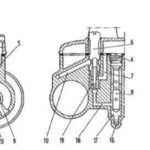
Section demonstration of the kind Weber carburetor Fiat 500 261MB 4 .
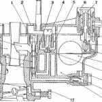
1 . Jet of air brake – 2 . Air intake – 3. Channel minimo4 mixture .
Idle jet holder – 5 . Minimum air hole – 6. inspection cap
filter – 7. Filter mesh -8 . Fuel inlet fitting
– 9. Needle Valve – 10 . Needle Valve – 11. pin
floating fulcrum – 12. Float – 13. Idle jet 14 .
Main jet holder – 15 . Main Jet – 16. bowl
Fuel – 17. Screw – in mixture at least -18 . minimum bore
to the duct – 19. Butterfly – 20 . Progression hole – 21. cone
speaker (not interchangeable ) – 22. Emulsion holes – 23. cockpit
emulsion – 24. Centering mixture (not interchangeable )
– 25 . Hose sprayer.
Sections demonstration starter carburetor Fiat 500 Weber type 26 4 1MB .
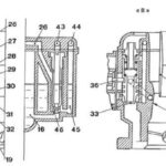
2 . Air intake. 16 . Fuel tank » 19 . Butterfly - 21. Cone Speaker - 24 . Centering mix - 26. Channel mix 27 . thinning of the air hole 28. Channel commissioning efficiency · 29. Forum mixture of formal efficiency - 30. Forum mixture Starter - 31. Forum commissioning efficiency · 32. 33 hole starter mixture • starter valve 34 . channel mix Starter - 35. Holes air starting device - 36. Barbell - 37. Spring return lever device starting 38 . start lever device 39. Screw fixing the starter control cable - 46 . Cover with support sheath command avvlamento  41 . Valve spring starter - 42 . Retention and spring guide » 43 . Air jet hole emulsion Starter - 44. Air hole emulsion ponetto reserve - 45 . Cockpit reserve of goodwill - 46 . Starting jet
A. device B. Device · fully inserted partially lnserltc 'C. The device completely off.
Got to start the engine of the Fiat 500 , the device delivers a mixture reason and in such quantities as to allow the smooth operation of the engine cold , but the engine warms up , the mixture is way too rich and too much : it is therefore necessary progressively exclude the starter with increasing engine temperature.
During this maneuver, the valve (33 ) gradually uncovers the hole (27 ) , which allows a further influx of air from the hole of the spring guide (42 ) , so as to lean the mixture delivered by the device , while , progressively covering the holes ( 30 ) and (32) and j the air holes (35 ) , it decreases as the quantity : in this way the device delivers a mixture under much poorer and in quantities less, the smaller is the degree of insertion of the device same (Scheme ‘B’ of Fig. 40).
The hole of the mixture ( 29 ), the channel (28) and the hole (31 ) formed in the diffuser (21) , have the task of allowing a smooth progression of acceleration even when the engine is cold: opening the throttle (19 ) to increase the engine speed , there is a reduction of the vacuum acting on the channel ( 34 ) , which would cause the reduction of the amount of fuel delivered through the same channel , resulting in irregular progression of acceleration ; however through the hole ( 31 ), the channel ( 28) and the hole ( 29) , from which air is drawn in at closed throttle , mixture is called up by the vacuum . states in the restricted section of the speaker as a result of the opening of the butterfly, thereby compensating for the decreased supply through the channel . (34) With the starter off , the valve (33) also covers the hole ( 29) preventing the recall of mixture (Diagram “C” in Fig. 40).
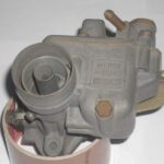
CARBURETOR FIAT 500 GIARDINIER A WEBER 26 OC
From the diagram of operation in Fig . 42 it is noted that the fuel coming from the tank (23 ) , through the channel (35 ) reaches the starting jet (37 ) . Pulling full stroke the command of starting device using the lever ( 31) , the valve cone (30 ) is raised from its sealing seat and flow in the fully open position (position “A” of Fig . 42 ) : in these conditions the valve (30 ) turns out to be the channel of the mixture ( 28) that the channel starting mixture (29 ) . With the throttle position of idling , depression , due to the intake of the engine driven by the starter motor, causes the fuel , which is located in the housing of the jet (37 ) , in the jet itself and in the cockpit of reserve (36 ) , are emulsions with the air coming from the air jet (38 ) . Through the channel (28 ) the mixture comes through the channel (29 ) downstream from the throttle , together with the air sucked from the holes (34 ) , allowing a ready starting of the engine .
Sections demonstration of Weber carburetor Fiat 500 Giardiniera 26 OC .
1 . Fuel inlet connector - 2 . Filter mesh - 3. Inspection cap filter - 4. Jet of air brake - 5 . Outlet . 6.Portagetto air idle - 7. Duct minlrno > 8 . Emulsifier tube 9 . Centering mix - 10 . Minimum 11 - channel mix . Cone dlffuscre » 12 . · Progression hole 13 . · Minimum bore to the conduit 14 . Idle mixture adjusting screw -15 . Butterfly Valve - 16. Pan - cockpit communication channel - 17. Well casing pipe for frothing - 18. Channel cornunicazione well - idle jet - 19. Idle jet - 20 . Tube nozzle - 21. Holes emulslone -22 . Main Jet - 23. Fuel tank - 24. Float - 25 . • float pivot pin 26. Needle Valve - 27. Needle valve.

Sections demonstration of Weber carburetor Fiat 500 Giardiniera 26 OC on the starter.
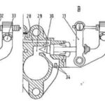
23 . Fuel tank - 28. Channel rnlscela » 29. · 30 channel starter mixture . Starter valve 31 . Lever operative part of goodwill - 32. • Starter control cable device 33 . Screw fixing sheath - 34. Air holes of emulsi -35 . Communication channel pan - starting jet - 36. Cockpit reserve of goodwill - 37. Starting jet -38 . Jet of air brake starter • 39. Slit air emulsion cockpit reserve .
A. device B. Device • fully inserted partially inserted - C. device completely off.
Got to start the engine of the Fiat 500 , the device delivers a mixture reason and in such quantities as to allow the smooth operation of the engine cold , but the engine warms up , the mixture is way too rich and too much : it is therefore necessary progressively exclude the starter with increasing engine temperature. During this maneuver, the valve (30 ) gradually covers the hole in the channel of the mixture ( 28 ) so as to lean the mixture delivered by the device , while progressively clog the channel (29 ) , gradually reducing the quantity of mixture delivered by the carburetor ; in this way the device provides a mixture under much poorer and in quantities less, the smaller is the degree of insertion of the device itself (position ‘B ) of Fig . 42 .
With the starting device is switched off , the valve (30 ) closes the channel of the mixture ( 29) preventing the recall of fuel (position ‘C’ of Fig . 42 ) .
Rules for use of the starter device
To get from the starter to progressive operation all the benefits that it can provide , please observe the following rules of use:
STARTER MOTOR FIAT 500
Cold start: fully insert the starter (position ‘ A) of Figs. 40 and 42 ) . Starting when the engine semicaldo : in this case 3 5 7 6 it is sufficient to partially insert the starter (position “B” in Figs. 40 and 42).
PUTTING IN EFFICIENCY OF FIAT 500
During the heating period , the engine , even with the engine running , disconnect the device progressively with successive maneuvers , so you always have a supply of extra mixture is strictly necessary for the smooth operation of the engine ( location “B” in Figs. 40 and 42 ) .
NORMAL OPERATION OF VEHICLE
As soon as the engine has reached a sufficient temperature for a smooth operation , turn off the ignition device (position “C” in Figs. 40 and 42).
REGISTRATION OF MINIMUM
To register the minimum necessary to act on the adjustment screw on the pace and adjusting the mixture. The adjusting screw allows to graduate gait throttle opening ; screw , conical tip of the register of the mixture , has the task of regulating the ‘ amount of the mixture coming from the channel of the minimum , which mixes with the air sucked from engine through the existing lights between the wall of the main duct and the butterfly in the minimum position , thus allowing to obtain the title mixture more convenient for a regular operation of the engine . The minimum registration must be done with the engine warm and running, initially adjusting the minimum opening of the throttle to a value such that the motor support with safety . It then proceeds to search for the dosing mixture that gives the pace faster and more stable for that throttle position , it still reduces the throttle opening to idle more convenient, then rechecking the mixture strength .
RULES FOR THE FLOAT LEVELLING
To make Iivellatura float is necessary to observe the following general rules :
– Make sure that the seat (3 , figs. 43 and 44) of the needle valve is securely screwed into the housing , interposed with the crank .
– Keep the lid ( 1 ) of the carburetor in a vertical position , as the weight of the float ( 9 ) would lower the movable ball (8 ) mounted on the needle ( 4 ) .
– With carburetor cover and vertical tab ( 6) of the float in light contact with the ball ( 8) of the pin (4) , float (9) must be within 7 mm , for motor 1100.000 (fig. 43) and 7 mm , 5 , 120,000 for the motor ( fig. 44 ) , from the plane of the cover with gasket ( 2 ) mounted and well adhering to the same .
A Iivellatura carried out to check the float switch (9 ) race to the bottom has to be distant from the cover , respectively, 14.5 mm and 15 mm , if necessary, change the location of the Appendix (5). When the float ( 9 ) was not exactly set , change the position of the tongue ( 7 ) of the float itself up to reach the required height , taking care that the tab ( 6 ) of contact is perpendicular to the axis of the pin ( 4 ) and which is not present on the contact plane , nicks which may affect the free flow of the pin itself.
– Check that the float (9) can rotate freely about its fulcrum .
WARNING
If it becomes necessary to replace the valve seat pin (3, Figs. 43 and 44 ), you must ensure that your new home is well screwed into the housing , fitting a new seal and repeating leveling .
L'officina per le vostre Fiat 500 d'epoca
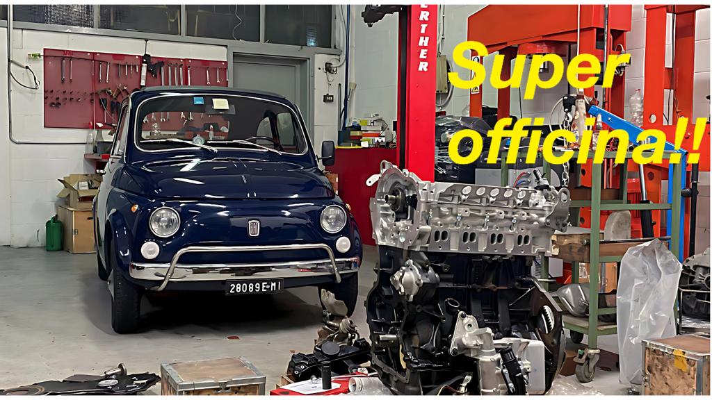
Raramente ho trovato tanta cura e passione come in questa officina. Ne parlo in questo articolo. Se siete vicino a Milano e vi serve una squadra di bravissimi meccanici per la vostra Fiat 500 d'epoca questo è il loro contatto: tel +39 338 776 7046, Via Fanfulla da Lodi, 01, Trezzano sul Naviglio, MI


However, it was unpublished and edited in 2012, so it may show
2012 as the published date online.
Ma… la traduzione giapponese è inciampata. Non si capisce nulla. Volevo solo sapere come regolare il carburatore.
Mi spiace molto, questo è quello che riusciamo a fare….